
DOC023.53.90143
sc1000 Controller
Enhanced Communications
MANUAL
12/2018, Edition 3

3
Table of contents
Section 1 Specifications ................................................................................................................................ 5
Section 2 General information..................................................................................................................... 7
2.1 Safety information ............................................................................................................................................... 7
2.2 Overview of product ............................................................................................................................................ 7
Section 3 Installation ....................................................................................................................................... 9
3.1 User requirements .............................................................................................................................................. 9
3.2 General requirements associated with remote maintenance .............................................................................. 9
3.2.1 Requirements associated with the sc1000 controller ................................................................................ 9
3.2.2 Requirements associated with the computer............................................................................................. 9
3.2.3 Scope of delivery ..................................................................................................................................... 10
3.3 Overview of the various connection options ..................................................................................................... 10
3.4 Establish an Ethernet connection ..................................................................................................................... 12
3.4.1 Establish a basic Ethernet connection..................................................................................................... 13
3.4.2 Establish an Ethernet connection with secure VPN tunnel...................................................................... 14
3.5 Install a VPN tunnel .......................................................................................................................................... 15
3.5.1 Requirements associated with the sc1000 controller .............................................................................. 15
3.5.2 Requirements associated with the computer........................................................................................... 15
3.5.3 sc1000 controller: Install the VPN client using an SD memory card ....................................................... 15
3.5.4 sc1000 controller: Install the VPN client using a web browser ................................................................ 17
3.5.5 sc1000 controller: Install the VPN client using Windows Explorer/FTP................................................... 20
3.5.6 sc1000 controller: Check VPN installation............................................................................................... 22
3.5.7 Computer: Install the VPN client.............................................................................................................. 23
3.5.8 Establish a VPN connection between the sc1000 controller and the computer ...................................... 24
3.6 Establish a GPRS connection........................................................................................................................... 25
3.6.1 Hardware requirements associated with the sc1000 controller ............................................................... 26
3.6.2 Software settings for the sc1000 controller ............................................................................................. 26
3.6.3 GPRS connection without VPN tunnel .................................................................................................... 27
3.6.4 Establish a GPRS connection with secure VPN tunnel .......................................................................... 27
3.7 Establish a GPRS connection via fixed IP VPN server .................................................................................... 28
3.8 GPRS connection via a VPN server of the mobile network operator ............................................................... 29
3.9 GPRS connection via fixed IP service and VPN server of the mobile network operator................................... 30
3.10 Optional Modbus TCP expansion ................................................................................................................... 30
3.10.1 Requirements associated with Modbus TCP......................................................................................... 30
3.10.2 sc1000 controller software settings ....................................................................................................... 31
3.10.3 Configure the Modbus TCP software module on the sc1000 c
ontroller ................................................ 32
3.10.4 Configure the Modbus telegram ............................................................................................................ 33
3.10.5 System configuration example using Unity Pro ..................................................................................... 37
Section 4 Error messages ........................................................................................................................... 41
4.1 GSM/GPRS....................................................................................................................................................... 41
4.2 VPN tunnel ........................................................................................................................................................ 41
4.3 Modbus TCP ..................................................................................................................................................... 41
4.4 Notification by e-mail in the event of error messages/warnings........................................................................ 42
4.4.1 sc1000 controller software settings ......................................................................................................... 42
4.4.2 E-mail format ........................................................................................................................................... 43
Section 5 Replacement parts and accessories................................................................................... 45
Section 6 Glossary ......................................................................................................................................... 47

4

5
Section 1 Specifications
Specifications are subject to change without notice.
* USA
The transmitter contained within this product is a ”Quad Band” device that can operate in the
850 / 900 / 1800 / 1900 MHz bands. The use of this device is not authorized for operation with GSM Bands 900 / 1800 MHz in
US & Canadian Territories.
This transmitter is authorized for use in either fixed or mobile locations.
Antennas used with this product must be located such that operation of this device is at least 20 cm (7.9 in) away from all
persons and must not be Co-Located with any other transmitting antenna.
The user is not authorized to use any antenna other than that provided by the manufacturer and shall not exceed 2.89 dbi for
GSM 1900 and 1.33 dbi for GSM 850 Mhz.
FCC ID: QIPMC55i
IC #: 7830A-MC55i
CE per Notified Body#: CE 0681
* EUROPE
CAUTION
• Do not operate the device in hospitals and/or near medical instruments such as cardiac pacemakers or hearing aids.
• The device cannot be used in hazardous locations.
• Do not operate the device in the proximity of combustible gases, steams or dust.
• Do not operate the device near highly combustible areas such as gas stations, fuel depots, chemical plants and blasting
works.
• The device can cause disturbances when in the proximity of television sets, radios or PCs.
• Do not expose the device to strong vibrations or impacts.
• Using the GSM services (SMS messages, data communication, GPRS etc.) is likely to incur additional costs from a service
provider. The user is exclusively responsible for any damages and costs incurred.
• Do not use or install this equipment in any manner other than that specified in this manual. Inappropriate use will void the
warranty.
• Any change of the equipment is inadmissible and leads to the loss of the operating permission
• In addition to the safety considerations, obey all the regulations specific to the country in which the device is being operated.
sc1000 controller display module
*GSM/*GPRS modem
The sc1000 display module with integrated GSM/GPRS modem transfers data, SMS
and GPRS services to GSM networks.
The sc1000 controller supports the GSM frequency bands:
850 / 900 / 1800 / 1900 MHz
Supports GPRS multislot class 10 and the GPRS coding schemes:
CS-1, CS-2, CS-3 and CS-4.
Modbus TCP server
The Modbus TCP server exhibits "conformance class 0".
This class supports the following function codes:
Read Multiple Registers (FC 3)
Write Multiple Registers (FC 16)
The following function codes are also supported:
Read/Write Multiple Registers (FC 23)
Read Device Information (FC 43/14)
Ethernet port Ethernet RJ45, 10 MB/s
Warranty
Warranty 1 year

6
Specifications

7
Section 2 General information
2.1 Safety information
Please read the entire manual carefully before installing the software. Further information
regarding the sc1000 controller is provided in the sc1000 controller manual.
2.2 Overview of product
The sc1000 controller is designed for Internet-based communication with other users.
The Ethernet port (wired connection) or the GSM/GPRS modem (wireless connection)
serves as the communication interface for the sc1000.
The wired connection via the Ethernet port (used to be service port) is established using
a LAN cable. If necessary, the optional sc1000 outdoor Ethernet port kit can be used to
afford additional protection to the Ethernet port when the sc1000 controller is used
outdoors. sc1000 controllers are also frequently installed in areas unsuitable for a wired
Internet/network connection. Mobile communications networks are a viable option for
collecting data and controlling the sc1000 controller remotely. This "M2M" solution
(M2M = machine to machine) integrates the sc1000 controller in a local IT network via a
GPRS mobile communications network.
A VPN tunnel makes sure that communication between the sc1000 controller and the IT
network is secure.
Once the LAN or GPRS connection has been established, no further steps are necessary
on the sc1000 controller.
The sc1000 controller is configured via a computer web browser. It is also possible to
download data logs/upload software updates in this way.
The optional Modbus TCP software module enables the sc1000 controller to be
integrated directly in PLC systems (PLC = programmable logic controller). PLC systems
record data measured by the sc1000 controller and process this data further.
Note: Any software not programmed and distributed by the manufacturer will not be supported. For
details contact the provider.
Notice
Network and access point security is the responsibility of the customer that uses the wireless
instrument. The manufacturer will not be liable for any damages, inclusive however not limited to
indirect, special, consequential or incidental damages, that have been caused by a gap in, or
breach of network security.

8
General information

9
Section 3Installation
3.1 User requirements
Only appropriately trained specialist personnel are authorized to install and operate the
computer system and sc1000 controller. Users must possess sound knowledge of
network technology and computer systems.
3.2 General requirements associated with remote maintenance
Every specified requirement must be fulfilled, otherwise remote maintenance and/or
browser-based access to the sc1000 controller will not be possible, and damage to the
system may occur.
3.2.1 Requirements associated with the sc1000 controller
All safety information and instructions provided in the sc1000 controller manual must be
observed.
Additional requirements:
Browser password allocation
A browser password must be assigned before the Ethernet/GPRS connection is set up to
make sure browser-based access to the sc1000 controller is possible.
1. Select SYSTEM SETUP>BROWSER ACCESS>PASSWORD from the main menu of
the sc1000 controller.
2. Assign a browser password.
Assessment of GPRS availability at location
GPRS must be available at the sc1000 controller's location for this to be accessible
via GPRS.
Note: The availability of GPRS must be ensured at the controller's location.
Installation of Modbus TCP software module
If Modbus TCP support is used, the Modbus TCP software module must be licensed and
an activation key provided.
3. To activate either a trial- or permant license enter SYSTEM SETUP>LICENSE
MANAGEMENT.
3.2.2 Requirements associated with the computer
The computer to be connected to the sc1000 controller must be capable of establishing a
workable Internet connection.
The following requirements must be fulfilled:
• The user account used to log in to the computer must be assigned administration
rights
• A web browser must be installed
• An Internet connection must be available
SYSTEM SETUP
BROWSER ACCESS
PASSWORD
10
Installation
3.2.3 Scope of delivery
The following components are included in the scope of delivery:
• VPN client software tailored to the sc1000 controller
• Manual
Note: Please contact the manufacturer or responsible representative immediately if either of the
components listed above are missing or defective.
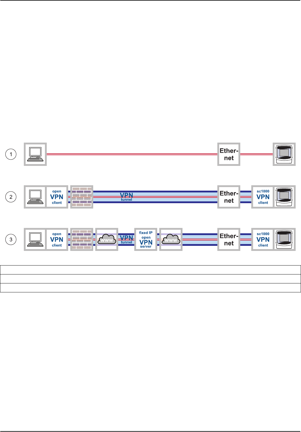
3.3 Overview of the various connection options
There are several ways to establish a connection between the sc1000 controller and a
computer. Examples of the following types of connection are illustrated in Figure 1 and
Figure 2:
• Ethernet-based connection
• GPRS-based connection
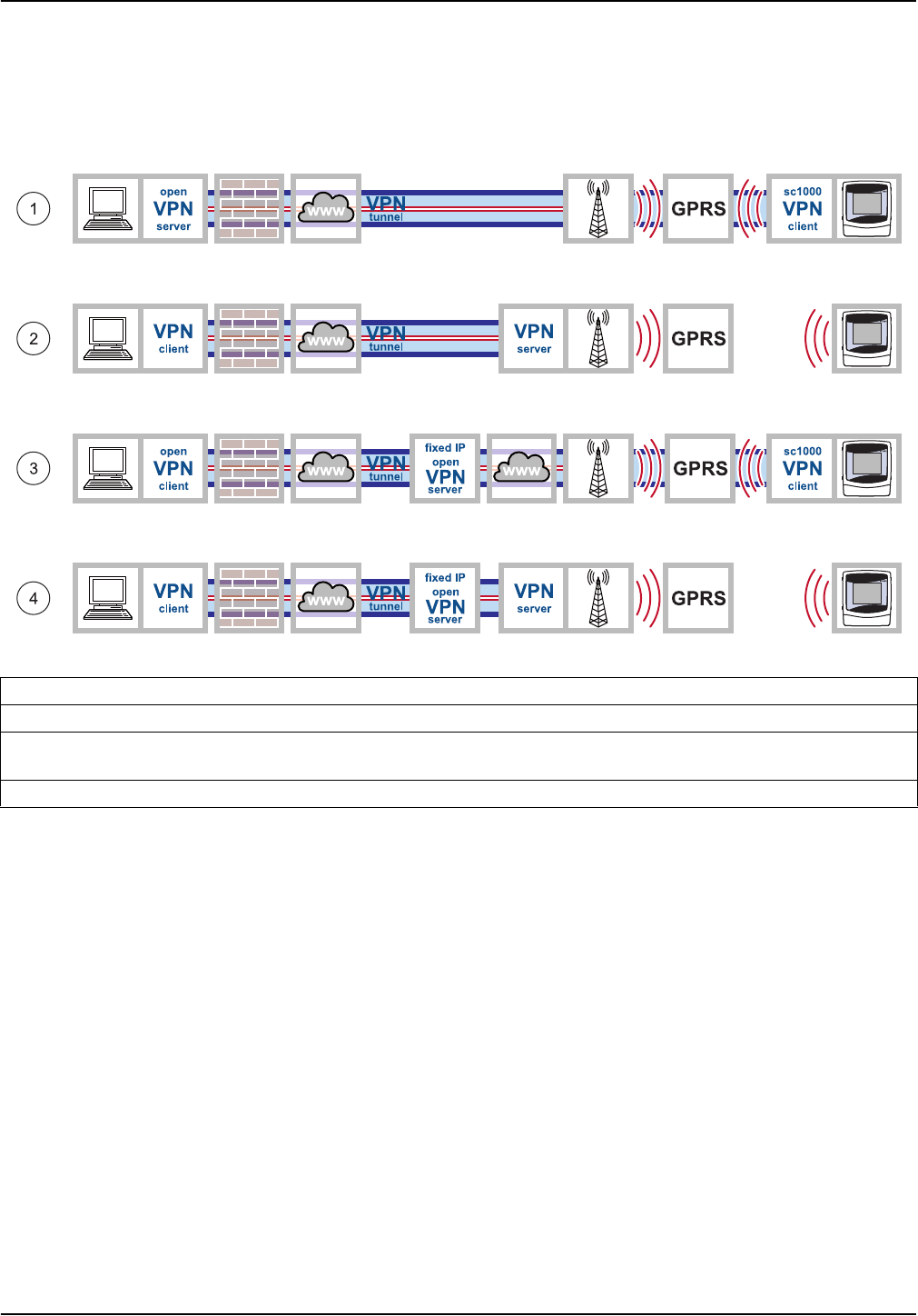
Figure 1 Overview of alternative Ethernet-based connections
1 Basic Ethernet connection
2 Ethernet connection with secure VPN tunnel
3 Ethernet connection via fixed IP VPN server
11
Installation
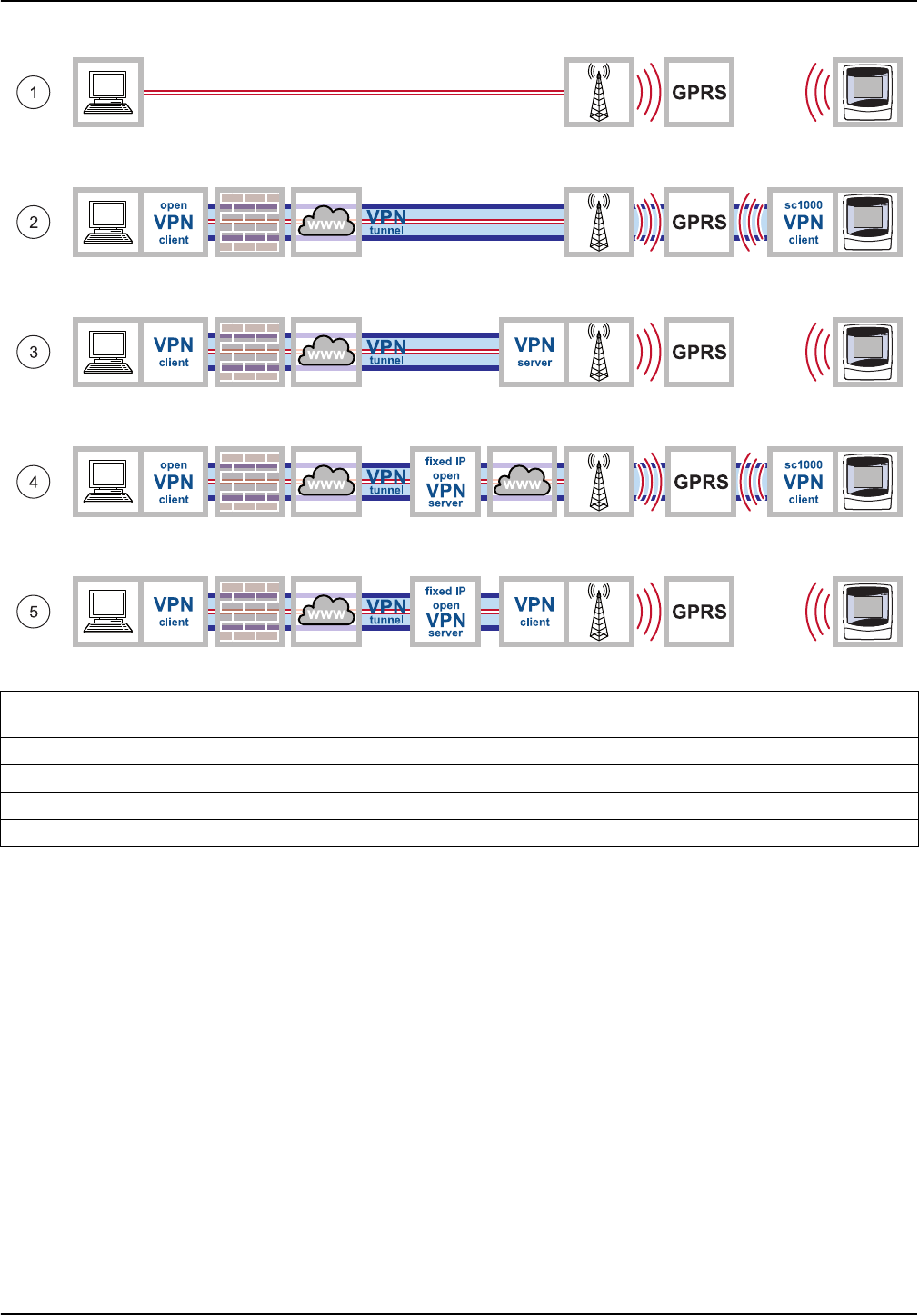
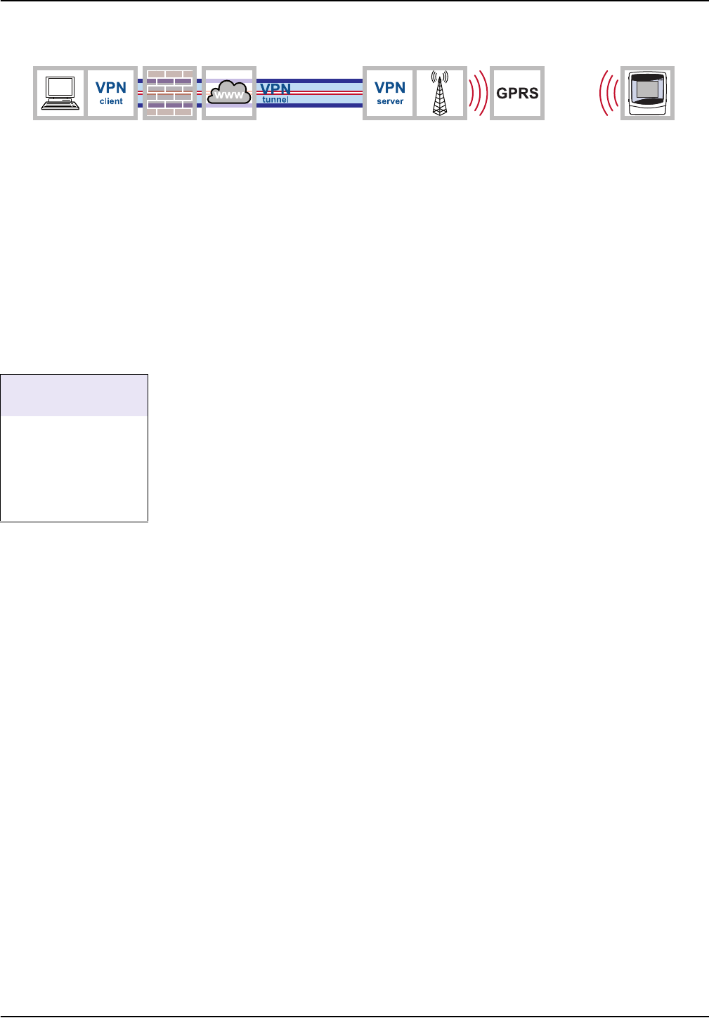
Figure 2 Overview of alternative GPRS-based connections
1 GPRS connection without VPN tunnel (only possible if a CDA (Corporate Data Access) account is set up with the mobile
network operator)
2 GPRS connection with secure VPN tunnel
3 GPRS connection via a VPN server of the mobile network operator
4 GPRS connection via fixed IP VPN server
5 GPRS connection via a fixed IP service and VPN server of the mobile network operator
12
Installation
3.4 Establish an Ethernet connection
The Ethernet connection is the wired connection between a computer and the Ethernet
port on the sc1000 controller. This Ethernet port is a 10 MB/s Ethernet connection located
on the display module.
A direct connection between the computer and the sc1000 controller is established as
follows:
Via basic Ethernet connection
(Figure 3, point 1)
Scope of application: The sc1000 controller is located within the corporate network or
used for testing purposes.
Via Ethernet connection with secure VPN tunnel
(Figure 3, point 2)
Scope of application: The sc1000 controller is outside of the corporate network.
Via Ethernet connection with fixed IP VPN server
(Figure 3, point 3)
Scope of application: The sc1000 controller is accessible via the Internet from any
location with a fixed IP address.
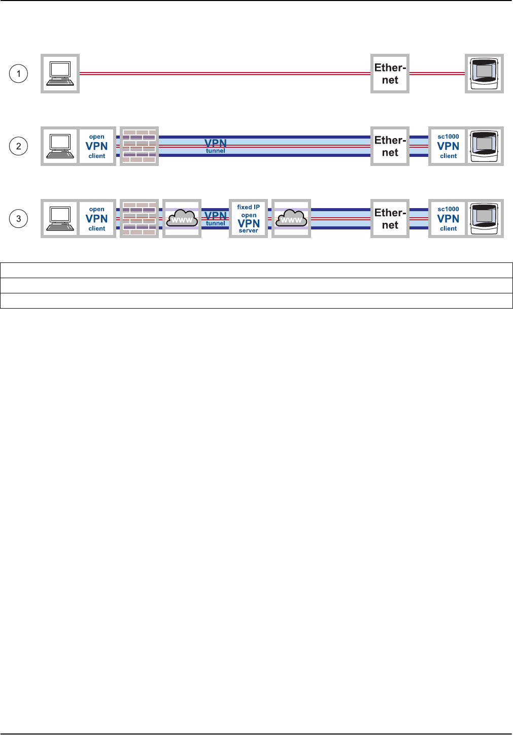
Figure 3 Ethernet connections
1 Basic Ethernet connection
2 Ethernet connection with secure VPN tunnel
3 Ethernet connection with fixed IP VPN server
13
Installation
3.4.1 Establish a basic Ethernet connection
If the sc1000 controller is located within the corporate network or is used for testing
purposes, a basic Ethernet connection without VPN between the devices is advisable
(Figure 4).
1. Connect the computer to the corporate network using an Ethernet cable. Make sure
the Internet connection is fully functioning. Open various Internet pages to test the
connection.
2. Connect the sc1000 controller to the network by inserting an Ethernet cable into the
RJ45 Ethernet port (Figure 5).
3. Select SYSTEM SETUP>BROWSER ACCESS from the sc1000 controller main
menu to configure network settings.
4. Request the following settings from the IT department if configuring network settings
manually:
• IP ADDRESS
• NETMASK
• DNS IP
• GATEWAY
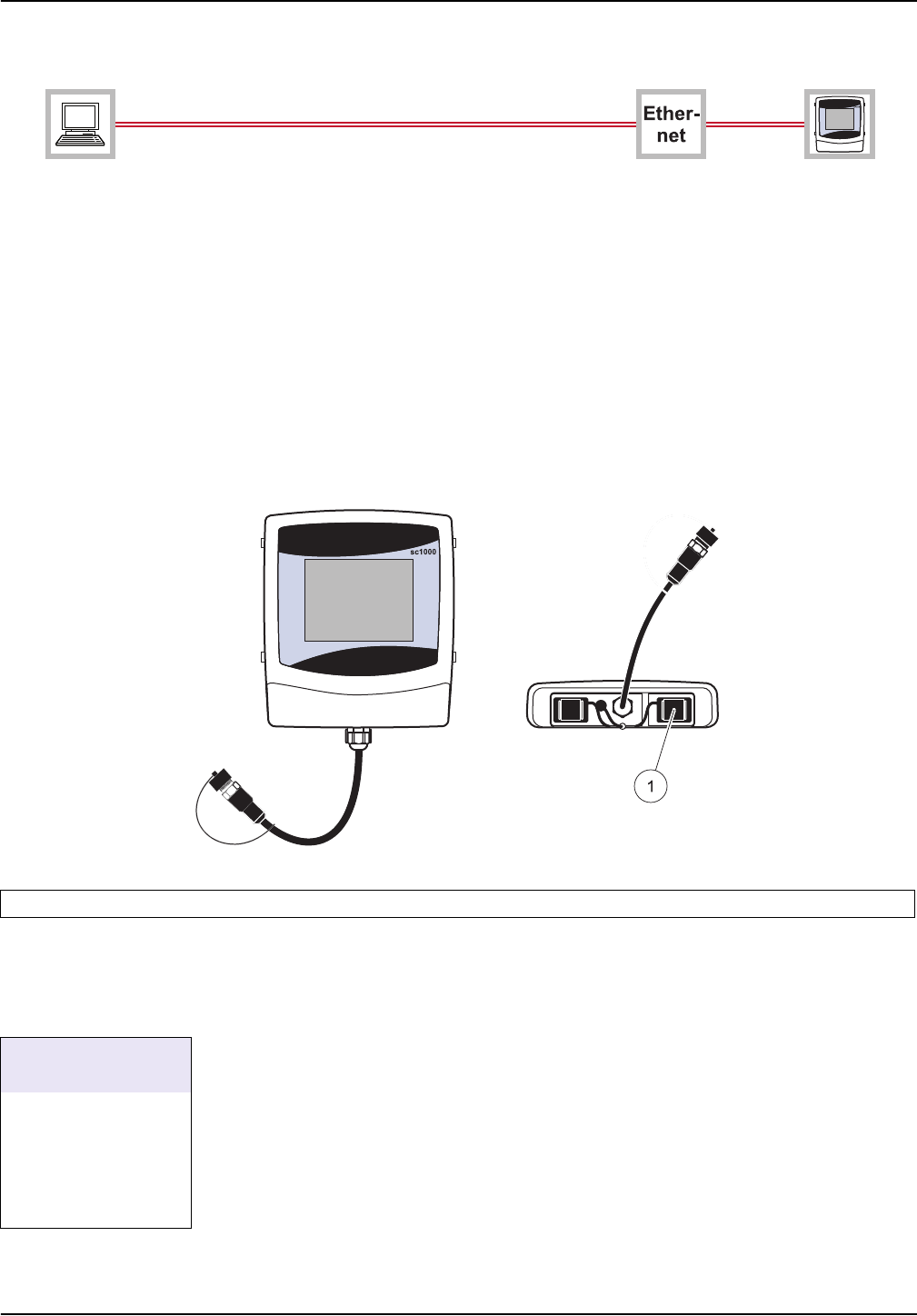
Figure 4 Basic Ethernet connection
Figure 5 Ethernet port on sc1000 controller display module
1 Ethernet port (used to be service port) on display module
SYSTEM SETUP
BROWSER ACCESS
IP ADDRESS
NETMASK
DNS IP
GATEWAY
DHCP
14
Installation
5. Configure the DHCP setting as follows for automatic configuration:
• DHCP: ON
6. Open a web browser on the computer. Enter the IP address of the sc1000 controller
in the address bar (refer to point 3.). The login page for the sc1000 controller is
displayed (Figure 6).
7. Enter the browser password (refer to Figure 6 and Section 3.4.1, page 13).
Note: A browser password is essential for web browser-based access to the sc1000 controller.
The Ethernet connection between the computer and the sc1000 controller has now been
established.
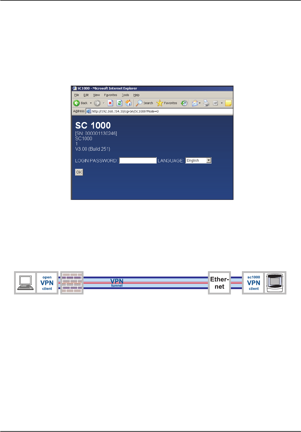
3.4.2 Establish an Ethernet connection with secure VPN tunnel
If the sc1000 controller is outside of the corporate network, an Ethernet connection with a
VPN tunnel is required (Figure 7). Information on setting up a VPN tunnel is provided in
Section 3.5, page 15.
Figure 6 Login page for sc1000 controller
Figure 7 Ethernet connection with secure VPN tunnel

15
Installation
3.5 Install a VPN tunnel
If the sc1000 controller is outside of the corporate network, a virtual private network
(VPN) must be installed between the computer and the sc1000 controller. The VPN
makes sure that the computer and sc1000 controller can communicate within a secure
channel (tunnel) that is protected from unauthorized access.
Windows 2000 and Windows XP both provide a built-in VPN server. However this only
enables a single connection to be made between an sc1000 controller and the computer
at any one time. For several connections to run simultaneously, a separate stand-alone
VPN server is required.
Depending on the design of the VPN connection, the VPN server is provided by a mobile
network operator/Internet service provider or the IT department. The design must be
planned thoroughly before installation.
3.5.1 Requirements associated with the sc1000 controller
The sc1000 controller requires a specific VPN software package that must be purchased
from the manufacturer. There are several ways to install the VPN software package on
the sc1000 controller:
• Using an SD memory card
• Using a web browser
• Using Windows Explorer/FTP data transfer
3.5.2 Requirements associated with the computer
The freeware VPN software "OpenVPN" must be installed on the computer (refer to
Section 3.5.4, page 17).
3.5.3 sc1000 controller: Install the VPN client using an SD memory card
The sc1000 controller display module includes a build-in slot for SD cards. One of the
functions of the SD card is to update the controller software. Further information
regarding the use of SD memory cards is provided in the sc1000 controller manual.
An SD memory card containing the VPN client software tailored to the sc1000 controller
can be purchased from the manufacturer (refer to Section 5, page 45).
Note: Only use SD cards with a maximum memory size of 1 gigabyte for installation.
1. Create the following directories on the SD memory card (if not yet created):
• DEV_SETTINGS
• SC1000
• UPDATE
2. Copy the following files to the UPDATE directory on the SD memory card:
From manufacturer:
• Tailored VPN client software for sc1000
(if not already installed on the SD card contact the support of the manuafcturer)
16
Installation
From VPN server provider:
• Configuration file (e.g. file with ".ovn" extension)
• Certificate (e.g. file with ".crt" extension)
• Key file (e.g. file with ".key" extension)
3. Start sc1000 controller.
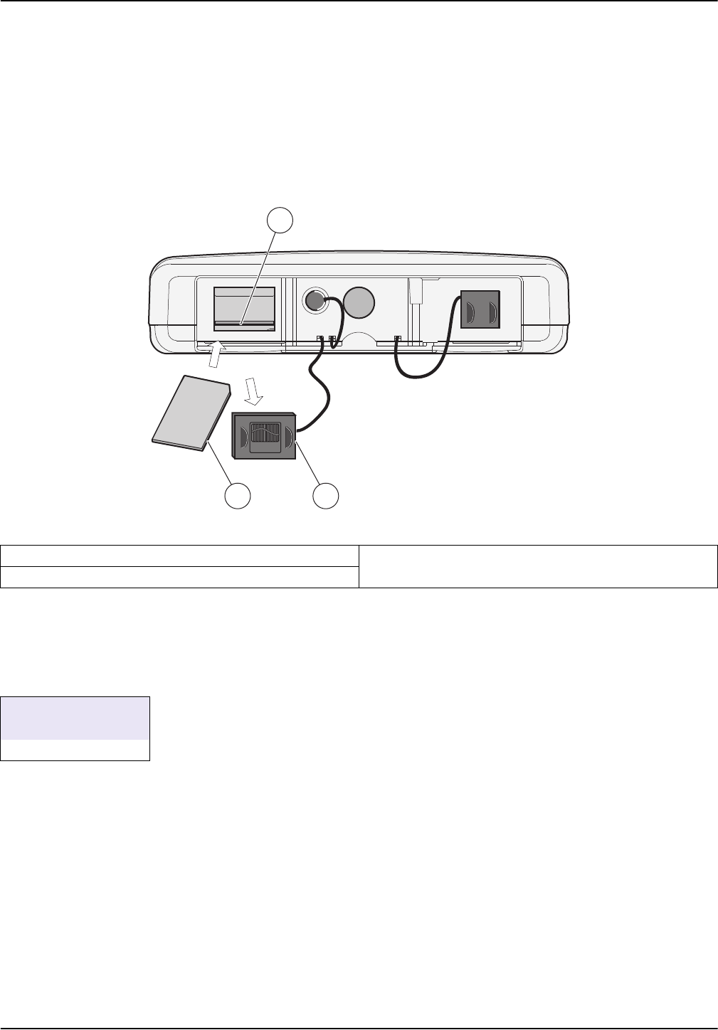
4. Remove the cover of the SD card slot on the sc1000 controller display module
(Figure 8).
5. Insert the SD memory card into the SD card slot on the sc1000 controller.
6. Reattach the SD card slot cover.
7. Start the installation of the VPN client via SYSTEM SETUP>STORAGE
CARD>SOFTWARE UPDATE.
The sc1000 controller installs and configures the VPN software automatically and must
then be restarted.
8. To confirm the VPN configuration enter SYSTEM SETUP>BROWSER
ACCESS>VPN.
Figure 8 Underside of display module
1 SD card slot 3 SD memory card
2 SD card slot cover
1
2
3
SYSTEM SETUP
STORAGE CARD
SOFTWARE UPDATE
17
Installation
3.5.4 sc1000 controller: Install the VPN client using a web browser
Note: The web browser installed on the computer must support file transfer via FTP. Microsoft
Internet Explorer 7 only supports FTP protocol to a limited extent.
1. Make sure that the Ethernet connection between the sc1000 controller and computer
is fully functioning.
2. Make sure that the web browser used supports FTP.
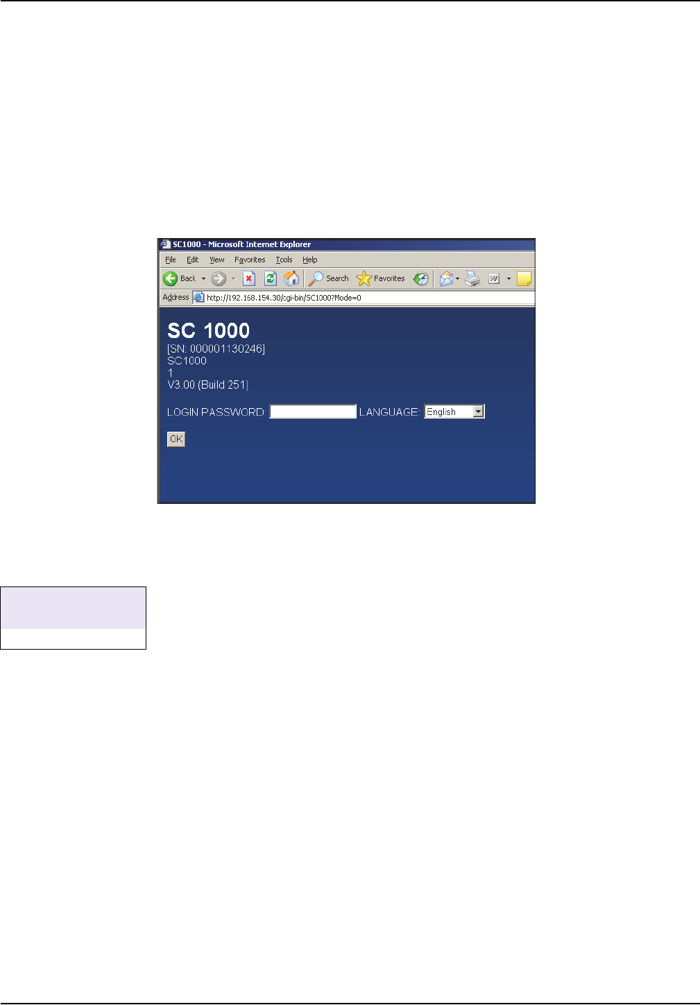
3. Open the web browser on the computer and enter the IP address of the sc1000
controller into the address bar (Figure 9).
4. The login page for the sc1000 controller is shown.
The IP address of the sc1000 controller can be found under
SYSTEM SETUP>BROWSER ACCESS>IP ADDRESS.
5. Enter the browser password (refer to 3.4.1, page 13).
Note: A browser password is essential for web browser-based access to the sc1000 controller.
Figure 9 Login page for sc1000 controller
SYSTEM SETUP
BROWSER ACCESS
IP ADDRESS
19
Installation
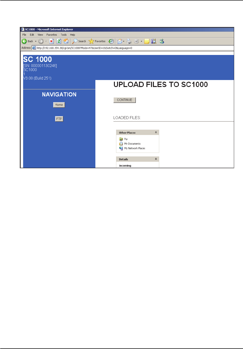
8. The "Upload files to sc1000" screen is displayed and the file manager interface
(e.g. Microsoft Windows Explorer) is integrated into the browser window.
9. Click on ftp under FILES UPLOADED in the browser window.
10. Open the file manager (e.g. Microsoft Windows Explorer) and select the following
files. These must be stored on the hard disk, the network or a mobile data carrier:
From manufacturer:
• Tailored VPN client software
From VPN server provider:
• Configuration file (e.g. file with ".ovn" extension)
• Certificate (e.g. file with ".crt" extension)
• Key file (e.g. file with ".key" extension)
Figure 12 Upload files to sc1000 controller
20
Installation
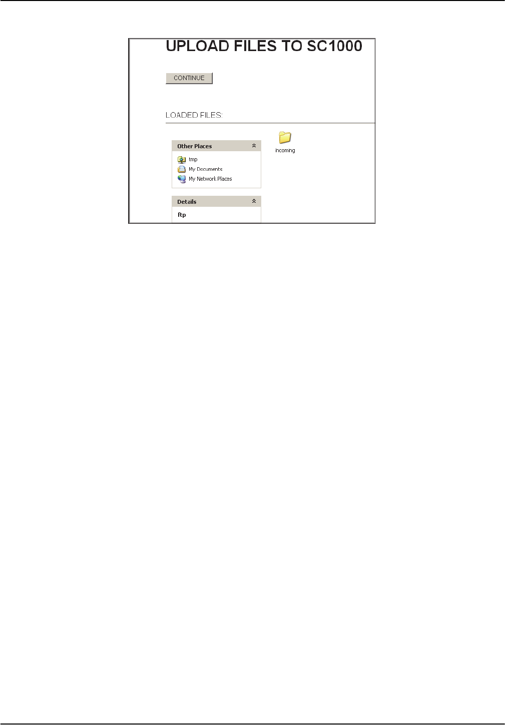
11. Copy the files and paste into the incoming directory in the web browser (Figure 13).
12. Press the
CONTINUE button.
13. Confirm the update on the sc1000 controller screen.
The sc1000 controller now installs and configures the software automatically and must
then be restarted.
3.5.5 sc1000 controller: Install the VPN client using Windows Explorer/FTP
If the web browser does not support FTP protocol, data transfer via FTP in Windows
Explorer is a viable alternative.
1. Close the web browser (if still open).
2. Open Windows Explorer.
3. Enter the following FTP address into the address bar in Windows Explorer:
ftp://<IP address of sc1000 controller>/tmp/incoming
Example: ftp://192.168.154.30/tmp/incoming
4. Press the
ENTER key to confirm the FTP connection.
5. Open the file manager (e.g. Microsoft Windows Explorer) and select the following
files. These must be stored on the hard disk, the network or a mobile data carrier:
From manufacturer:
• Tailored VPN client software
From VPN server provider:
• Configuration file (e.g. file with ".ovn" extension)
• Certificate (e.g. file with ".crt" extension)
• Key file (e.g. file with ".key" extension)
Figure 13 Transfer files
21
Installation
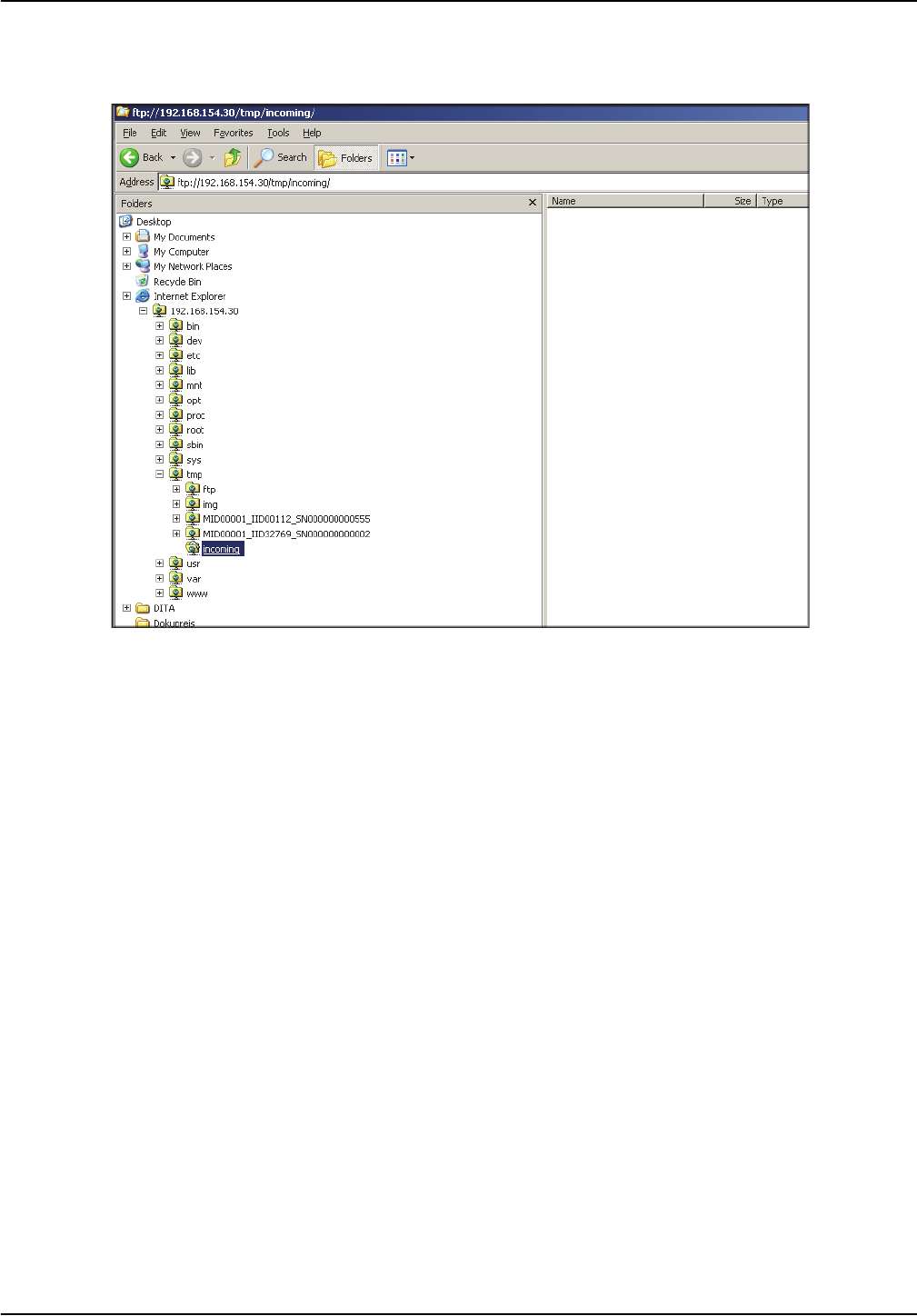
6. Copy the selected files to the following FTP directory:
<IP address of sc1000 controller>\tmp\incoming (Figure 14).
7. Open the web browser on the computer and enter the IP address of the sc1000
controller into the address bar.
The login page for the sc1000 controller is shown.
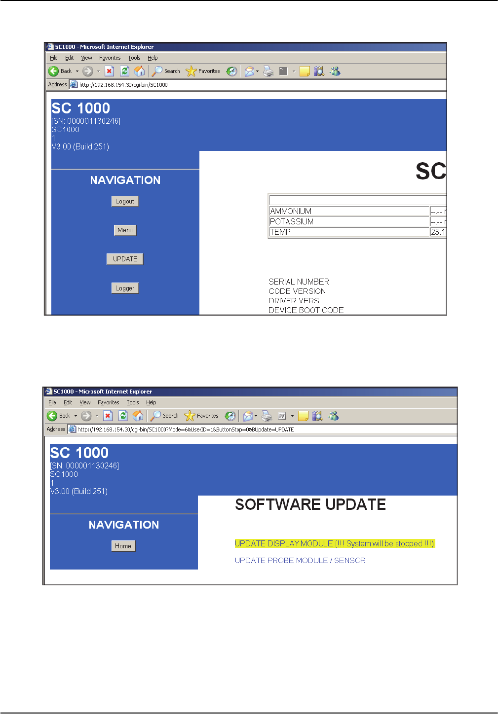
8. Enter the browser password.
9. Press the UPDATE button.
10. Click on the UPDATE DISPLAY MODULE link.
11. Confirm the update on the sc1000 controller screen.
The sc1000 controller now installs and configures the software automatically and must
then be restarted.
Figure 14 FTP data transfer in Microsoft Windows Explorer

22
Installation
3.5.6 sc1000 controller: Check VPN installation
1. Open the web browser on the computer and enter the IP address of the sc1000
controller into the address bar.
2. Enter the browser password (refer to 3.4.1, page 13).
3. On the SYSTEM SETUP>BROWSER ACCESS>VPN screen, make sure that the
VPN tag is set to LAN.
4. On the SYSTEM SETUP>BROWSER ACCESS screen, make sure that the VPN tag
is set to CONNECTION.
5. On the SYSTEM SETUP>BROWSER ACCESS>VPN>CONFIG FILE screen, make
sure that no tags are highlighted red.
Red tags indicate errors (refer to Section 4, page 41).
Light gray tags indicate information that is already included in the configuration and
can be ignored.
6. Enter the USERNAME and PASSWORD on the SYSTEM SETUP>BROWSER
ACCESS>VPN screen if requested to do so by the VPN server provider. These
details must be supplied by the VPN server provider.
SYSTEM SETUP
BROWSER ACCESS
VPN
VPN
SYSTEM SETUP
BROWSER ACCESS
VPN
CONFIG FILE
23
Installation
3.5.7 Computer: Install the VPN client
In order to communicate with the sc1000 controller via a VPN tunnel, a VPN client must
also been installed on the computer.
Important Note: If a VPN client is required on the sc1000 controller to establish a
connection, OpenVPN must be installed as the VPN client on the computer. OpenVPN is a
free VPN solution supported by several operating systems. The software can be
downloaded from http://www.openvpn.net.
1. Install OpenVPN on the computer (following the installation instructions provided with
the software).
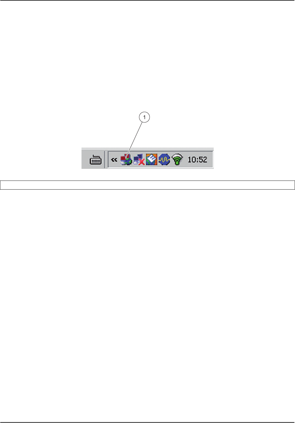
The OpenVPN icon appears in the taskbar on the desktop following installation
(Figure 15).
2. Copy the following files to the OpenVPN directory:
From manufacturer:
• Tailored VPN client software
From VPN server provider:
• Configuration file (e.g. file with ".ovn" extension)
• Certificate (e.g. file with ".crt" extension)
• Key file (e.g. file with ".key" extension)
3. Start OpenVPN.
Figure 15 OpenVPN icon in the taskbar
1 OpenVPN icon
24
Installation
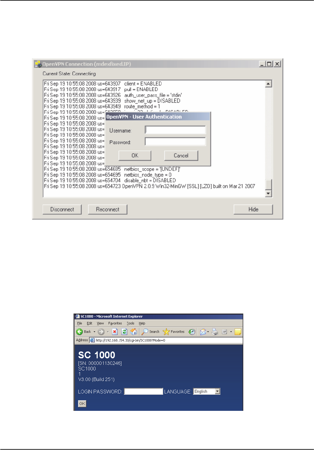
3.5.8 Establish a VPN connection between the sc1000 controller and the computer
1. Start OpenVPN on the computer.
2. Enter username and password (Figure 16). These are supplied by the VPN server
provider.
3. Enter the IP address (supplied by VPN server provider) of the sc1000 controller in the
web browser on the computer (Figure 17).
Note: The IP address can be found in the SYSTEM SETUP>BROWSER ACCESS>
VPN>IP ADDRESS menu on the controller.
Note: OpenVPN on the computer is not provided by the manufacturer. For details contact the VPN
server provider.
Figure 16 Establish connection in OpenVPN
Figure 17 Login page for sc1000 controller
25
Installation
4. Enter the browser password (refer to Section 3.4.1, page 13).
The computer and sc1000 controller are now connected via a secure VPN tunnel.
3.6 Establish a GPRS connection
GPRS is a packet-oriented data service based on the established GSM mobile
communications standard. GPRS enables users to transfer data on the move. In this form
of data transfer, individual batches of data are converted into small data packets, in which
they are subsequently sent. These packets are then reconstructed upon receipt.
If GPRS is activated on the sc1000 controller, there is a seemingly permanent connection
with the receiver ('always-on' operation). However, a radio channel is not opened until
data is actually transferred. Use of a GPRS service is billed not by the duration of the
connection, but by the volume of data sent.
The mobile station (i.e. the sc1000 controller) is assigned a temporary, dynamic IP
address that uniquely identifies it. From the user's point of view, the device is accessed
via this IP address, as is customary on the Internet.
GPRS enables the sc1000 controller to establish an Internet-based connection through
which communication with other Internet users is possible.
The IP address assigned when using GPRS is not usually accessible directly from the
Internet. As a result, requests sent by a GPRS device (e.g. the sc1000 controller) can
only be routed as far as the Internet. Only at that point does the network operator
authorize the response to be routed from the Internet to the GPRS device.
Figure 18 GPRS connections
1 GPRS connection with secure VPN tunnel
2 GPRS connection via a VPN server of the mobile network operator
3 GPRS connection via fixed IP VPN server (only possible if a CDA (Corporate Data Access) account is set up with the
mobile network operator)
4 GPRS connection via a fixed IP service and VPN server of the mobile network operator

26
Installation
All GPRS connections are managed via a mobile network operator. The following types of
GPRS connection are detailed in this manual (Figure 18):
• GPRS connection with secure VPN tunnel
(Figure 18, point 1)
• GPRS connection via a VPN server of the mobile network operator (only possible if a
CDA (Corporate Data Access) account is set up with the mobile network operator)
(Figure 18, point 2)
• GPRS connection via fixed IP VPN server
(Figure 18, point 3)
• GPRS connection via a fixed IP service and VPN server of the mobile network
operator (Figure 18, point 4)
3.6.1 Hardware requirements associated with the sc1000 controller
The sc1000 controller must be equipped for mobile data communication:
• A GSM/GPRS modem must be installed.
• An antenna must be connected.
• A GPRS-enabled SIM card must be installed.
If applicable, the SIM card must have been configured to the mobile network
operator's specifications ( e.g. PIN modified).
Note: A suitable data volume agreement should be concluded with a mobile network operator.
3.6.2 Software settings for the sc1000 controller
• Assign a browser password in the SYSTEM SETUP>BROWSER
ACCESS>PASSWORD menu.
• Enter the PIN specified by the mobile network operator in the SYSTEM SETUP>GSM
MODULE>PIN menu.
• From the SYSTEM SETUP>GSM MODULE>GPRS menu
• Check whether the DIAL-IN NUMBER is identical to the number specified by the
mobile network operator
• Enter the APN (Access Point Name, provided by mobile network operator)
• Enter the USERNAME and PASSWORD (provided by mobile network operator)
• Set the GPRS tag to ON.
•
The sc1000 controller is now GPRS-ready.
SYSTEM SETUP
GSM MODULE
DIAL-IN NUMBER
APN
GPRS
USERNAME
PASSWORD
27
Installation
3.6.3 GPRS connection without VPN tunnel
A GPRS connection without a VPN tunnel is only possible if a CDA account has been set
up with a mobile network operator. If this is the case, only the software settings need to
be configured on the sc1000 controller (Section 3.6.2, page 26); configuration of the VPN
itself is part of CDA administration.
Without a CDA account, it is only possible to connect to the Internet. E-mails can be sent,
but access to the sc1000 controller is not possible with this type of connection.
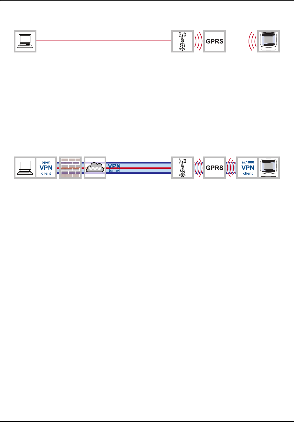
3.6.4 Establish a GPRS connection with secure VPN tunnel
1. Install the VPN client on both the computer and sc1000 controller as described in
Section 3.5, page 15.
2. Set the SYSTEM SETUP>BROWSER ACCESS>VPN>VPN tag to GPRS on the
sc1000 controller.
3. Under SYSTEM SETUP>BROWSER ACCESS>VPN, check whether
• The STATUS tag is set to CONNECTION
• An IP address is displayed in the IP ADDRESS tag
Note: This IP address is important and will have been specified by the VPN server provider.
This address will already have been set when the standard VPN Ethernet connection was
established.
Check connection
The GPRS connection with secure VPN tunnel has been established if:
• The GPRS CONNECTION tag is displayed under STATUS in the SYSTEM
SETUP>GSM MODULE>GPRS menu.
• An IP address has been assigned in the SYSTEM SETUP>GSM MODULE>GPRS
menu. This IP address must be assigned, however, it is not relevant beyond this
stage.
Figure 19 GPRS connection without VPN tunnel
Figure 20 Establish a GPRS connection with secure VPN tunnel
28
Installation
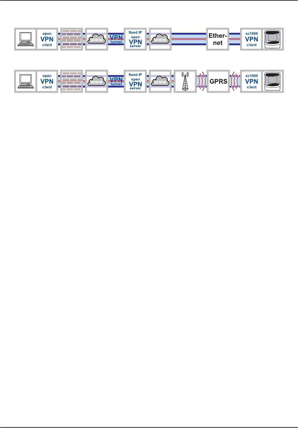
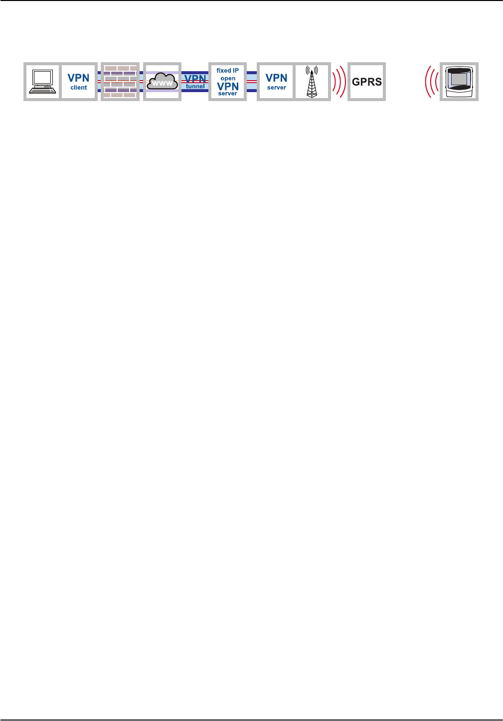
3.7 Establish a GPRS connection via fixed IP VPN server
There are problems associated with connecting a sc1000 controller within a corporate
network via a VPN tunnel. An external fixed IP service that assumes the roles of VPN
server and interface to the mobile network operator is therefore a viable alternative.
If a fixed IP service is used, the sc1000 controller is assigned its own fixed IP address,
from which it can be accessed via the Internet. This address does not change.
A fixed IP connection such as this can be Ethernet or GPRS-based (Figure 21). Costs
incurred for the use of GPRS/mobile network are billed based on the volume of data
transmitted and the frequency with which this occurs.
Figure 21 Establish a GPRS connection via fixed IP VPN server
29
Installation
3.8 GPRS connection via a VPN server of the mobile network operator
The mobile network operator's CDA service (Corporate Data Access service) is used the
transfer encrypted data between devices and the control center via GPRS. The corporate
network is connected to the mobile communications network in one of two ways: via a
rented line, which guarantees a fixed bandwidth and high degree of security, or via the
Internet. The connection between the corporate network and the mobile network operator
is established using a secure VPN tunnel.
The APN (Access Point Name), username and password are requested every time a
connection is established between the sc1000 controller and the computer. Users are
identified by the mobile network operator.
• From the SYSTEM SETUP>GSM MODULE>GPRS menu
• Check whether the DIAL-IN NUMBER is identical to the number specified by the
mobile network operator
• Enter the APN (Access Point Name, provided by mobile network operator)
• Enter the USERNAME and PASSWORD (provided by mobile network operator)
• Set the GPRS tag to ON
It is also possible to obtain a private access point (APN) within the network. If this option
is pursued, only machines with a specific SIM card profile can log on to the network via
this access point. The mobile network operator specifies the requirements associated
with configuring a private access point.
Figure 22 GPRS connection via a VPN server of the mobile network operator
SYSTEM SETUP
GSM MODULE
DIAL-IN NUMBER
APN
GPRS
USERNAME
PASSWORD
30
Installation
3.9 GPRS connection via fixed IP service and VPN server of the mobile
network operator
There are often problems associated with connecting to a company's own private
network. For this reason, fixed IP providers usually also offer this service.
The mobile network operator connects the user to the fixed IP provider via a private VPN
tunnel. The sc1000 controller does not require its own VPN client in this case. The user
requires VPN client software on his/her PC in order to connect to the fixed IP provider.
3.10 Optional Modbus TCP expansion
Modbus TCP is a standard for industrial communication. Through Modbus TCP,
computers can be connected to measurement and control systems that use the TCP/IP
protocol for data transmission. This form of data transmission is termed M2M
communication (M2M = machine to machine).
Note: In order to use the Modbus TCP software module, NO Modbus card must be installed in the
sc1000 controller.
The Modbus TCP software module enables the sc1000 controller to be integrated directly
in PLC systems (PLC = programmable logic controller). PLC systems record data
measured by the sc1000 controller and process this data further. Analysis of the data
received and the resulting actions are programmed in the PLC system.
3.10.1 Requirements associated with Modbus TCP
The Modbus TCP software module must be activated/licensed for use in the sc1000
controller.
Figure 23 GPRS connection via fixed IP service and VPN server of the mobile network operator

31
Installation
3.10.2 sc1000 controller software settings
The Modbus TCP software module is configured in the following sc1000 controller
menus:
SYSTEM SETUP
MODBUS TCP
MODBUS TCP Determines whether Modbus TCP is activated (ON) or not (OFF).
TCP PORT Determines the TCP port.
TELEGRAM Configures a slave based on individual data compilations from various devices.
MODBUS ADDRESS
Default value: 0
Determines the address (1 to 247) of the Modbus slave configured in the TELEGRAM menu.
VIRTUAL SLAVES
Default value: DEACTIVATED
Virtual slaves can be added. These are copies of actual devices and are configured in the
TELEGRAM menu. The Modbus addresses for these slaves are displayed directly to the right of
the configured slave's address. The Modbus address of the first configured device is displayed
directly to the right of the configured slave's address, the address of the second device is
displayed to the right of that, and so forth.
ACTIVATED: Slave copy is activated.
DEACTIVATED: Slave copy is deactivated.
DATA ORDER
Default value: NORMAL
Determines the byte sequence for transferring floating point values. A floating point value
consists of 4 bytes.
Note that this setting only relates to data of the configured slave.
SWAPPED: Swaps the first byte pair with the last byte pair.
NORMAL: The pairs are not swapped.
An incorrect setting in this menu can lead to slight deviations in the floating point values (shifted
by one register).
SIMULATION
Simulates two floating point values and errors/statuses to substitute an instrument. The first
floating point value passes through a ramp between limits set in the MINIMUM and MAXIMUM
menus.
SIMULATION
Default value: NO
Switches simulation on (YES) or off (NO).
DURATION
Default value: 10 minutes
Determines the time required by the first floating point value to pass through the entire range
between MINIMUM and MAXIMUM.
MAXIMUM
Default value: 100
Upper limit for first floating point value.
MINIMUM
Default value: 50
Lower limit for first floating point value.
ERRORS
Default value: 0
The value entered in this menu is set as the value in the first simulated register.
STATUS
Default value: 0
The value entered in this menu is set as the value in the second simulated register.
TOGGLE Changes the direction of the simulated ramp application.
STATUS Contains information for data transfer.
32
Installation
3.10.3 Configure the Modbus TCP software module on the sc1000 controller
1. Set the MODBUS TCP tag to ON in the SYSTEM SETUP>MODBUS TCP menu.
2. Set the TCP PORT tag to 502 in the SYSTEM SETUP>MODBUS TCP menu.
Note: It may be necessary to select an alternative port depending on the corporate firewall
configuration. The responsible IT department will provide the necessary information regarding
this.
3. Create the telegram on the SYSTEM SETUP>MODBUS TCP>TELEGRAM
configuration screen (refer to sc1000 controller manual or Section 3.10.4, page 33).
Note: The telegram defines which data points are transferred by the sc1000 controller, and in
what sequence this takes place. The data points and names are probe-dependent.
4. Make sure that the telegram address is entered under SYSTEM SETUP>MODBUS
TCP>MODBUS ADDRESS (default = 1).
Note: Devices at subsequent addresses are only responsive if
SYSTEM SETUP>MODBUS TCP>VIRTUAL SLAVES is set to ON.
5. Enter values in the SYSTEM SETUP>MODBUS TCP>SIMULATION menu to enable
the transfer of data to be tested.
6. Set the SYSTEM SETUP>MODBUS TCP>SIMULATION>SIMULATION menu to ON
to test the transfer of data.
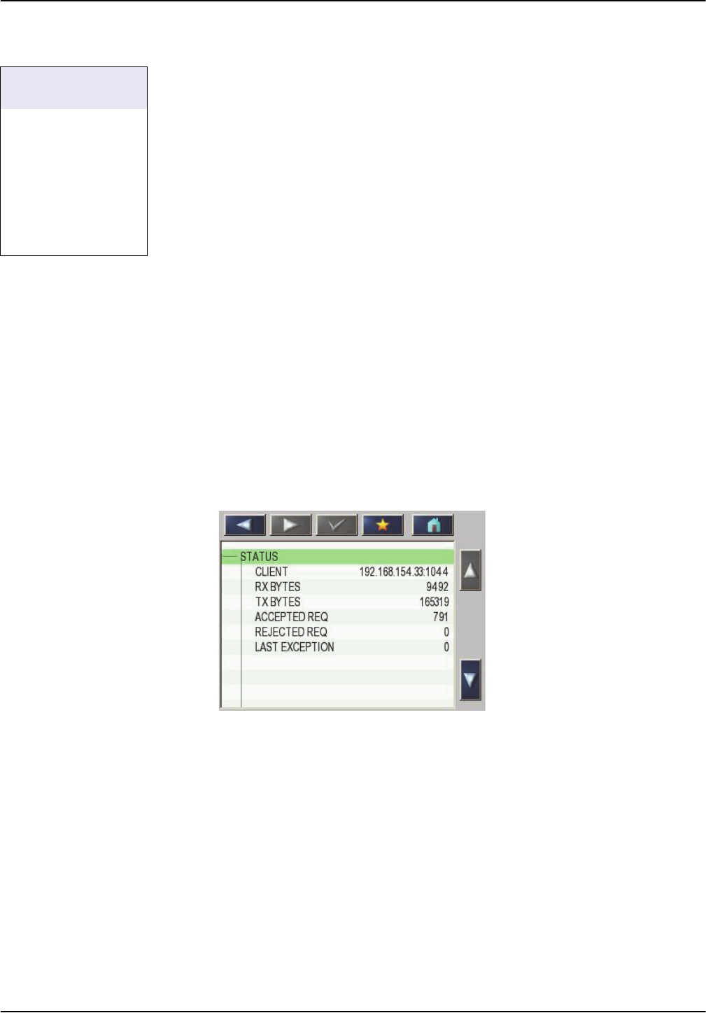
Information regarding the data transfer is displayed in the SYSTEM SETUP>MODBUS
TCP>STATUS menu (refer also to Table 4, page 41).
If all values have been set, the values transferred by the telegram can be queried and
processed further using any of the Modbus TCP clients.
A maximum of 5 Modbus TCP clients can be connected to the server at any one time.
If an additional Modbus TCP client attempts to establish a connection, the request will be
accepted but an existing connection will be lost as a result. The connection that has been
idle the longest is terminated.
SYSTEM SETUP
MODBUS TCP
MODBUS TCP
TCP PORT
TELEGRAM
MODBUS ADDRESS
VIRTUAL SLAVES
SIMULATION
STATUS
Figure 24 Modbus TCP status menu
33
Installation
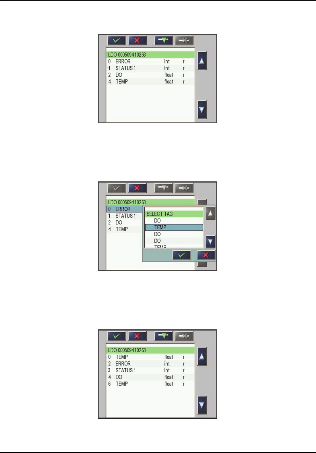
3.10.4 Configure the Modbus telegram
1. Select SYSTEM SETUP>MODBUS TCP>TELEGRAM.
2. The configuration screen is displayed (Figure 25).
3. Press
ADD and select a probe/device. The device selection window is displayed
(Figure 26).
SYSTEM SETUP
MODBUS TCP
TELEGRAM
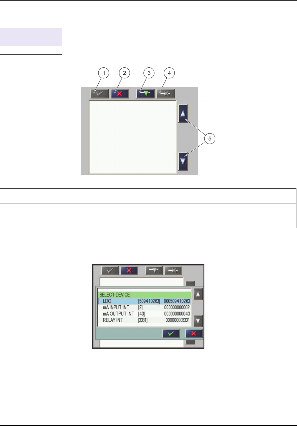
Figure 25 Configuration screen
1 ENTER button — Saves configuration and returns to the
FIELDBUS menu
4 DELETE button — Removes a device/tag from the
telegram
2
CANCEL button — Returns to the FIELDBUS menu
without saving
5 UP/DOWN arrow — Moves device/tag up and down
3
ADD button — Adds new device/tag to the telegram
Figure 26 Device selection window
34
Installation
4. Select a probe/device and press the ENTER button. The probe/device (including
serial number) is added to the telegram box (Figure 27).
5. Select a tag (e.g. error or status) and press the
ADD button. The tag selection box is
displayed with all tags that are available for the probe/device (Figure 28). The error
and status registers are identical for all probes/devices (Table 2 and Table 3).
6. Select tag and press the
ENTER button. The new tag is added to the telegram. Select
a tag and press the
UP and DOWN buttons to alter the position of the tag (Figure 29
and Table 1).
Figure 27 Device list
Figure 28 Tag selection window
Figure 29 Telegram list with new tag

35
Installation
7. Repeat steps to add additional probes/devices and tags.
8. Press the
ENTER button to save the configuration.
Table 1 Telegram list—Column description
Column Description
1
Data position in the configured Profibus slave (in 2 byte words)
Modbus: Data position in the configured Modbus slave
This slave contains holding registers beginning at 40001.
Example: "0" means register 40001 and "11" means register 40012.
2 Tag name to identify the configured data.
3
Data type
float=floating point value
int=integer values
sel=integer value resulting from an enumeration or selection list
4
Data status
r=data is read only
r/w=read/write
Table 2 Error register
Bit Error Description
0 Calibration error Faulty calibration detected
1 Electronic settings error Faulty electronic calibration/settings
2 Cleaning error Error in cleaning cycle detected
3 Measuring module error Error in measuring module detected
4 System initialization
Inconsistent settings detected, reset to factory
settings
5 Hardware error Faulty hardware detected
6 Internal communication error Internal communication error detected
7 Humidity error Excessive humidity detected
8 Excessive temperature Excessive temperature detected
9
10 Sample feed warning Error in sample feed detected
11 Questionable calibration warning Accuracy of previous calibration inadequate
12
Questionable measurement
warning
Accuracy of previous measurement inadequate/out of
range
13 Safety warning Safety equipment error detected
14 Reagent warning Reagent warning, e.g. fill level < min detected
15 Service request warning Service request detected

36
Installation
Table 3 Status register
Bit Status 1 Description
0 Calibration activated
Calibration in progress, measurement value not up to
date
1 Cleaning activated
Cleaning in progress, measurement value not up to
date
2 Service mode activated
Device in "Service" mode, measurement value not up to
date
3 General error message General error detected, refer to error text for details
4
Measurement value channel 0,
poor quality
Measurement accuracy is not within specified limits
5
Measurement value channel 0,
range short-fall
Measurement value falls short of the specified range
6
Measurement value channel 0,
range exceeded
Measurement value exceeds the specified range
7
Measurement value channel 1,
poor quality
Measurement accuracy is not within specified limits
8
Measurement value channel 1,
range short-fall
Measurement value falls short of the specified range
9
Measurement value channel 1,
range exceeded
Measurement value exceeds the specified range
10
Measurement value channel 2,
poor quality
Measurement accuracy is not within specified limits
11
Measurement value channel 2,
range short-fall
Measurement value falls short of the specified range
12
Measurement value channel 2,
range exceeded
Measurement value exceeds the specified range
13
Measurement value channel 3,
poor quality
Measurement accuracy is not within specified limits
14
Measurement value channel 3,
range short-fall
Measurement value falls short of the specified range
15
Measurement value channel 3,
range exceeded
Measurement value exceeds the specified range
37
Installation
3.10.5 System configuration example using Unity Pro
Note: Unity Pro software from Schneider Electric is the common IEC 61131-3 programming,
debugging and operating software for Modicon M340
TM
, Premium
TM
and Quantum
TM
. In case of
detailed questions please contact your local Schneider Electric support.
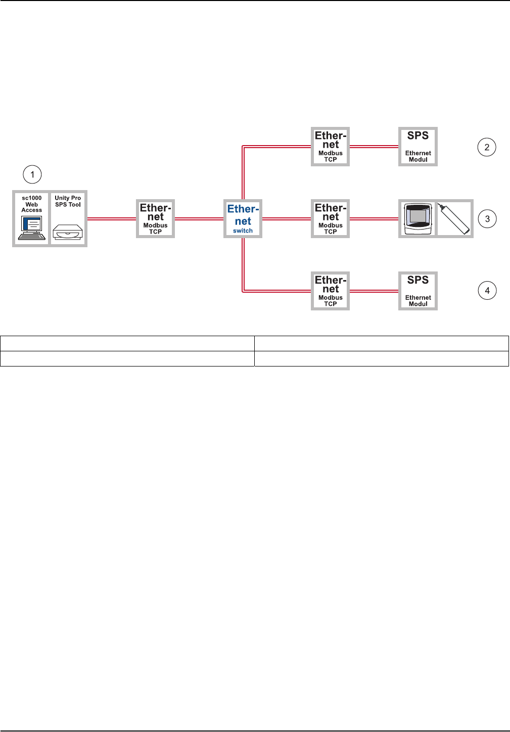
Figure 30 through Figure 32 illustrate how a system can be configured using the Unity
Pro PLC system software.
Figure 30 Overview of system configuration using Unity Pro
1 Engineering station with sc1000 WebAccess 3 sc1000 controller with probe
2 E.g. Telemecanique TSX Premium P57 4634M 4 E.g. Telemecanique Modicon Quantum CPU 65160
38
Installation
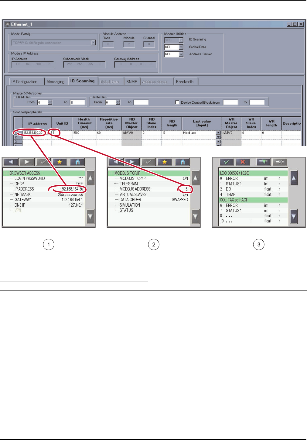
Figure 31 Connection of the sc1000 controller using Unity Pro
(The language of the menu entries depends on the language settings)
1 IP address 3 Content of telegram
2 Modbus address
39
Installation
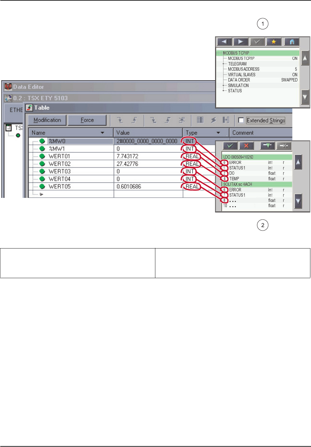
Figure 32 System configuration using Unity Pro
1 Data order swapped 2 Telemecanique TSX Premium P57 4634M starts with
offset 0
Telemecanique Modicon Quantum CPU 65160 with
offset 1

40
Installation

41
Section 4 Error messages
4.1 GSM/GPRS
See GSM error messages in the sc1000 controller manual.
There are no specific status messages for GPRS.
4.2 VPN tunnel
There are several status messages associated with establishing the VPN tunnel
connection. These are displayed under SYSTEM SETUP>BROWSER ACCESS>VPN:
• OFF: The OpenVPN client is deactivated
• LINK CONNECTION : The OpenVPN client is attempting to establish a connection to
the server.
• CONNECTION: A connection to the server has been established.
• INTERRUPTED: The connection to the server has been interrupted. This status is
displayed if the Internet connection is disrupted, e.g. the Ethernet cable is removed or
the GPRS connection is terminated. The connection is automatically established
again once the communication error has been resolved.
4.3 Modbus TCP
If an error occurs, the Modbus TCP server returns corresponding exception codes to the
querying client (Table 4).
The last exception code returned to each connected client is displayed in the SYSTEM
SETUP>MODBUS TCP>STATUS menu.
SYSTEM SETUP
BROWSER ACCESS
VPN
SYSTEM SETUP
MODBUS TCP
STATUS
Table 4 Modbus exception codes in accordance with Modbus specification
Exception code Designation
01 Illegal Function
02 Illegal Data Address
03 Illegal Data Value
04 Illegal Response Length
05 Acknowledge
06 Slave Device Busy
07 Negative Acknowledge
08 Memory Parity Error
10 Gateway Path Unavailable
11 Gateway Target Device Failed to Respond

42
Error messages
4.4 Notification by e-mail in the event of error messages/warnings
If an error occurs, an e-mail containing a description of the error can be sent to one or
more recipients. Up to four configuration sets can be created for e-mail notification.
Each configuration set includes the following (not exhaustive):
• The e-mail address of the recipient.
• Selected errors, warnings and events associated with connected probes that trigger
e-mail notification.
In order to use e-mail notification, an active connection is required between the sc1000
controller and computer (GPRS or Ethernet-based) . An e-mail account must also be set
up with an e-mail provider. This provider must support the sending of e-mails via an
SMTP server (outgoing mail server).
4.4.1 sc1000 controller software settings
E-mail notification is configured from the following sc1000 controller menus:
SYSTEM SETUP
E-MAIL
E-MAIL 1-4
E-MAIL ADDRESS
Specifies the e-mail address to which notifications are sent. Several e-mail addresses can be
specified. These must be separated by a space.
LANGUAGE Selects the E-MAIL language
E-MAIL LIMIT
(0–100)
Specifies the maximum number of e-mail notifications that the sc1000 controller can send
within a 24-hour period. The 24-hour cycle begins from the START TIME entered.
REPEAT
(0–24h)
Specifies the interval at which unconfirmed error messages are sent again to the E-MAIL
ADDRESS.
START TIME
Specifies the start time for the REPEAT function.
E.g.: REPEAT=6 h, START TIME=02:00: Unconfirmed messages are sent again at 02:00,
08:00, 14:00, 20:00.
INHIBIT
Default: OFF
ON: If the same error occurs more than once, e-mail notification is only sent for the first
instance.
CONFIGURE Specifies which devices are monitored and which error messages/warnings are sent by e-mail.
ADD
Adds devices to the configuration list. All connected devices are displayed, including the
sc1000 controller. Devices already added are grayed out and cannot be selected.
REMOVE Removes devices from the configuration list. All configured devices are displayed.
DEVICE NAME
1-n
Compiles individual messages for a device.
The ERRORS and WARNINGS menus contain all errors/warnings for the selected device.
1=An e-mail is sent in the event of an error/warning
0=An e-mail is not sent in the event of an error/warning
SELECT ALL: Activates (1) or deactivates (2) all menu options at once.
SENDER E-mail address of the sc1000 controller. Used to specify sender.
SMTP SERVER Outgoing mail server of e-mail provider. The server name is supplied by the e-mail provider.
USER NAME
User name for logging on to the SMTP server of the e-mail provider. The user name is
supplied by the e-mail provider.
PASSWORD SMTP server of the e-mail provider. The password is supplied by the e-mail provider.


44
Error messages

45
Section 5 Replacement parts and accessories
Description Cat. no.
SD card, 1 GB LZY520
HACH display module with GSM modem LXV402.99.01002
Outdoor Ethernet port kit LZY553
Ethernet cable RJ45 LZX998
Modbus TCP software module, license key LZY598

46
Replacement parts and accessories

47
Section 6 Glossary
Table 7 Glossary
Term Explanation
APN Access Point Name; enables access to an external packet data network.
DHCP
Dynamic Host Configuration Protocol; enables a new computer to be connected to an existing
network automatically.
DNS Domain Name System
Ethernet Physical layer for network communication, in accordance with IEEE standard 802.3.
Fixed IP server Server that assigns fixed IP addresses to end devices, and manages these.
FTP File Transfer Protocol
Gateway Networks based on different protocols can communicate with one another via gateways.
GPRS
General Packet Radio Service; packet-oriented transmission service that enables data and e-mail
to be sent using cell phones and computers.
GSM
Global System for Mobile Communications; second generation (2G) mobile communications
standard.
M2M Machine to Machine
Modbus TCP/IP Modbus protocol that is integrated in the TCP/IP protocol.
PLC Programmable logic controller
VPN
Software designed to connect devices running on a neighboring network to your own network
without the networks having to be compatible with one another. The network to which the devices
are connected is called an assigned network.
VPN client
Software that enables a device running on a network to access a secondary VPN network, i.e.
that provides a virtual simulation of the configuration of the assigned network.
VPN tunnel
Additional encryption of the original network packets within the VPN protocol to prevent
interception and manipulation.

48
Glossary

HACH COMPANY World Headquarters
P.O. Box 389, Loveland, CO 80539-0389 U.S.A.
Tel. (970) 669-3050
(800) 227-4224 (U.S.A. only)
Fax (970) 669-2932
www.hach.com
HACH LANGE GMBH
Willstätterstraße 11
D-40549 Düsseldorf, Germany
Tel. +49 (0) 2 11 52 88-320
Fax +49 (0) 2 11 52 88-210
www.de.hach.com
HACH LANGE Sàrl
6, route de Compois
1222 Vésenaz
SWITZERLAND
Tel. +41 22 594 6400
Fax +41 22 594 6499
© Hach Company/Hach Lange GmbH, 2009, 2011,2018
. All rights reserved. Printed in Germany 12/2018, Edition 3
